This is a Claus Bækkel idea. Now I have got some hardware working, he can port various text mode games to Colecovision.
Attach PS/2 keyboard to Colecovision.
Be cheap and simple.
Supply keycodes largely pre-cooked to Z80.
The Z80 can't directly bit-bang the keyboard lines. If the Z80 wasn't polling 100% of the time, it would miss keystrokes. Therefore we need something to deserialise and buffer scan codes. If we buffer them, we really need the means for the Z80 to indicate it has consumed a key and to move on to the next one. So the interface needs to be bi-directional.
The design attaches to the expansion connector. This provides access to the full Z80 bus, and power. This makes it easy to map in I/O ports visible to the Z80. Make the design pass through the connector signals, so that other add-ons may be connected.
I considered using the cartridge port. One approach would be to replace all the functionality of the existing MultiCart and Ultimate SD Cartridges, and then add keyboard functionality. Theoretically possible, but impractical, and hey, they've done a great job with these aready, why duplicate it. Another approach would be to be a pass-through, but the challenge with this is knowing how to do this without interfering with the memory accesses and banking systems used by these add-ons.
I considered interfacing via the controller port(s). This is similar to the approach employed by the "Roller Controller" add-on. Electrically this is difficult as I would have no common ground signal through a shared power supply and power and ground are not passed through the controller connectors. I considered how I might use opto-couplers between add-on and Colecovision but couldn't devise a scheme which worked. It is possible for an add-on to signal it is providing a keystroke instead of joystick information, by saying the Left and Right joystick buttons are pressed at the same time (impossible physically, possible electrically). However, I don't see an easy way for the Z80 to signal to the add-on, which implies we can't have a keyboard buffer.
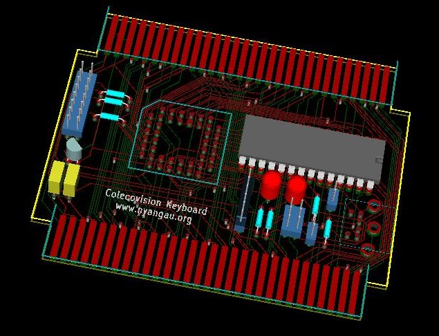
I used KiCad to prepare this circuit diagram. When placed and routed, you get :-

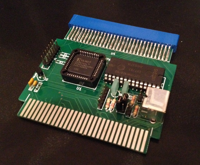
The finished board looks like this :-

I've added the all.tar.gz library of extra converted
parts from
http://library.oshec.org/
to my installation of KiCad.
I also have my own extra cv.lib containing the expansion
edge-connector components.
Both male and female forms are needed - male reflects the exposed edge of the
circuit board, like the Colecovision main board has, and female reflects
what an edge-connector would be soldered to.
The male component has most signals as inputs, the female component provides
most signals as outputs.
Otherwise, they're the same.
A L78L33 is used to regulate the 5V from the Colecovision to produce 3.3V, upto 100mA. Looking at the datasheets, the CPLD may use 60mA and the ARM around 10mA.
A XC9572XL is used for all the glue logic. This includes I/O address decoding, passing of data between Z80 and ARM and back again, and level shifting. CPLD pins are in short supply, so I can only address decode 6 bits of address (ie: match 4 ports at once). Also I can only pass 3 bits of command from Z80 to ARM, which is not an issue as I only need a few commands. Where the CPLD drives the databus with the keyboard data, I am relying on the 3.3V VOL and VOH being good enough for 5V TTL. This CPLD has :-
The XC9572XL is the largest I could find in a PLCC44 package. Interestingly, its cheaper than an XC9536XL (36 macrocells).
I tried to fit my VHDL for decoding the keyboard input stream into a CPLD but it wouldn't fit. Instead, I use an LPC1114 to decode and buffer the input stream. This chip has :-
LPC1114FN28 with Open Source Tools describes a simple setup with an LPC1114. ARM Cortex-Mx QuickStart describes getting a toolchain set up. These were a great help getting started with this chip.
"Bare metal" compiler build available from Linaro.
# cd /opt
# tar -jxf /work/downloads/gcc-arm-none-eabi-4_7-2013q1-20130313-linux.tar.bz2
lpc2lisp-master.zip programmer available from
LPC21ISP with LPC1114FN28/102 support.
# cd /opt
# unzip /work/downloads/lpc2lisp-master.zip
# cd lpc2lisp-master
# ae Makefile
   remove -static compiler option
   remove .out suffixes
   backout the latest edit
# make
lpc1114-blink-master.zip available as a starting point.
I considered using a Teensy USB Development Board. I even ordered a Teensy 3.0. You can think of this as a more powerful ARM (MK20DX128 ARM Cortex M4, 48MHz, 128KB Flash, 16KB RAM 2KB EEPROM) and USB programmability, conveniently packaged on a DIP sized board. However, its quite a bit more expensive. I don't think I need the extra processing power for the task at hand. Why pay for the USB hardware on every one, when one FTDI friend can be used for all the LPC1114s I might buy.
I also considered building the capture half of a keylogger, per Open source DIY hardware keylogger. This uses an AT89C2051, which is a 5V part, with 2KB Flash, 128B RAM, 15 GPIOs, in at DIP20 package. They're cheaper than the ARM, but are a lot smaller, and are 8 bit 8051 based. I do envisage mapping from PS/2 keyboard scan codes to ASCII codes in the ARM, thus making the Z80's life easier.
There are two jumpers. The first selects the UK or US keyboard layout. At the moment, the second doesn't have an official use.
There are two LEDs, intended to reflect caps lock and num lock state.
The design also includes a jumper for a Xilinx platform cable (to program the CPLD in-situ) and a jumper for a FTDI-friend (to program the ARM in-situ).
Sullins E[EBC]C30DRYN-S13 edge-connector from Digikey. Part number implies 30x2 pins, 0.1" spacing, 0.425" (longest) pin length, no mounting. E for tin contacts, B for gold, C for thicker gold. Ordered gold contact variety.
Manufacture the PCB at iteadstudio. I use the 10pcs 1.6mm HASL 100% e-test option.
The ARM deserialises the bitstream from the PS/2 keyboard. It does this bit by bit, at interrupt time, to ensure a low latency response to the PS2_CLK signal going low.
Strangely, I have seen spurious interrupts when PS2_CLK goes high, so the interrupt routine filters out these false positives. This could be noise on the PS2_CLK signal, or ground bounce, but if it is it must be shorter than what my 16MHz logic analyser can pick up. Either that, or a bug/quirk in the LPC1114 GPIO interrupt handling.
The interrupt routine also responds to I/O writes from the Z80, and captures the 3-bit keyboard command value which has been supplied.
Decoding scan-codes to keys, responding to keyboard commands, and updating the LEDs is done at user level. This disables interrupts, gets the next scan-code or keyboard command, reenables interrupts, then does the work in a leisurely and interruptable way.
The scan-code to keycode conversion is basically table driven. If the SW0 is high on startup, these tables are tweaked to reflect the US keyboard layout.
Subsequent keycode cooking (processing) keeps track of the shift keys, control keys, alt keys, caps-lock state (as toggled by the Caps Lock key) and num-lock state (as toggled by the Num Lock key). Keycodes are adjusted to reflect these things.
Although this may not be standard/obvious, Ctrl+Backspace is converted into keycode 127 (otherwise there would be no way to generate this traditional hard delete code).
A small reminder that unlike other special keys, you need to press Ctrl+Break before the keyboard actually sends the scan-code.
Access to the keyboard is via ports 030H..033H.
The Z80 outputs a command to the keyboard port. The ARM may not respond for a variable length of time. When it has processed the command, the data visible inputting from the port reflects the command received.
eg: To initialise the keyboard :-
KB_INIT:
        LD      A,KC_INIT
        OUT     (P_KBD),A       ; send init
KB_INI2:
        CALL    KB_INP          ; wait until its done
        CP      KD_INIT
        JR      NZ,KB_INI2
        RET
KB_INP keeps reading the port until it gets the same value
twice, so as to cope with the different ARM and Z80 clock domains.
High KD_ data values reflect the completion of the
various KC_ command values.
Low KD_ values are keycodes.
The special value KD_NONE means no-key is ready,
and the special value KD_RELE means key-release.
The release of a key is communicated as KD_RELE
followed by the keycode of the key being released.
Raw scan codes are cooked, and most normal key presses are returned as keycodes reflecting the current shift, capslock, ctrl and alt status. Their keycodes will be below 0A0H.
Special keys are supplied using higher keycodes. eg: F1, Home, NumLock, Left, LeftShift, CapsLock, LeftCtrl, LeftAlt, LeftWindows.
Even though cooking occurs, note that presses and releases of the shift keys, caps lock key, ctrl keys and alt keys are still returned.
A simple program only interested in ASCII would process keycodes below 080H. One interested in Alt+X keycodes too would process keycodes below 0A0H. One that was interested in special keys too would process all keycodes.
See testrom/TESTROM.MAC and testrom/CVKBD.INC
in the downloadable package for example code to use the keyboard.

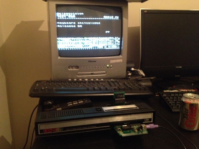
The test ROM first initialises the keyboard. It displays the last key press or release it has received. It also shows the last keyboard data byte read from port 030H on the right hand side.
The bottom third of the screen is filled with character graphics corresponding to the keycode value. Control+keys have the same character graphic as the key, except a spot is added to the bottom left of the graphic. Alt+keys have the same character graphic as the key, except a spot is added to the bottom right of the graphic. Byte values that don't correspond to a keycode have a graphic looking like a small dot. Byte values too high to be a keycode, that are used as a part of the protocol between the CPU and keyboard, are shown with a little NC character graphic.
As a key is pressed the corresponding character graphic background turns red, and when the key is released, the background turns green. In this way you can check that every key is correctly translated to its keycode.
If the i key is pressed, the test switches from a loop
which waits for each key to be pressed into a mode where it tests to see if
a key is ready, and if not, increments a counter.
This is much like INKEY$ or getch().
This is an alternative test ROM. Its not really intended for testing the keyboard, as it relies on this working. Instead it allows you to input from or output to ports, and read from and write to memory. It also allows you to call a location in memory.
You can use it to check out whats in memory or how other hardware is responding before you launch your own code. Remember that the keyboard passes through all the signals on the expansion edge-connector, allowing other expansion hardware to be connected.
Any Colecovision program able to use the keyboard can display this logo, provided by Claus :-

If you shop around :-
| Item | Where | Cost |
|---|---|---|
| PCB | iteadstudio | £2 |
| L78L33 | eBay | £0.33 |
| XC9572XL PLCC44 | Farnell | £2 |
| PLCC44 socket | Farnell | £0.50 |
| LPC1114FN28 | Mouser | £4 |
| Mini DIN 6 | RS Components | £2 |
| 30x2 edge-connector | Digikey * | £8 |
| Misc bits | £3 | |
| Total | £20 approx | |
Prices assume you buy enough parts for 10.
Note the edge-connector attracts an import fee.
To program the XC9572XL you need a Xilinx Platform cable.
To program the LPC1114, you need something like a "FTDI friend + extras", which can be sourced from Adafruit for $24 approx.
Full package downloadable from here.